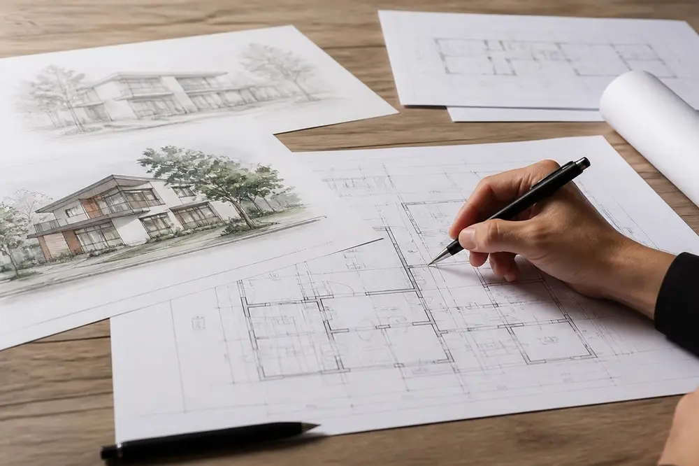
Detailed architectural drawings serve as the universal language between design vision and built reality. These comprehensive technical documents communicate every aspect of a building project, from structural frameworks to the smallest finishing details. For clients, contractors, and regulatory authorities alike, these drawings provide the clarity and precision essential for successful project delivery. Understanding the depth and complexity of detailed architectural drawings enables stakeholders to appreciate the meticulous planning required to transform initial concepts into tangible structures that meet both aesthetic aspirations and functional requirements.
The Foundation of Architectural Communication
Detailed architectural drawings represent far more than simple sketches or floor plans. They constitute a complete set of technical documentation that encompasses every measurable aspect of a building project. Architectural drawings have evolved significantly over centuries, progressing from hand-drawn illustrations to sophisticated digital representations that integrate multiple disciplines.
These drawings typically include plans, elevations, sections, and details at various scales. Each drawing type serves a distinct purpose within the broader construction documentation package. Plans show horizontal cuts through the building at specific heights, revealing room layouts and spatial relationships. Elevations display exterior and interior vertical surfaces, whilst sections cut through the building to expose internal construction details.
Scale and Precision Requirements
The accuracy demanded in detailed architectural drawings cannot be overstated. Different drawing types require specific scales to convey information effectively:
- Location plans: typically at 1:1250 or 1:2500 scale
- Site plans: commonly at 1:500 or 1:200 scale
- Floor plans and elevations: usually at 1:100 or 1:50 scale
- Construction details: often at 1:20, 1:10, or 1:5 scale
These scaled representations ensure that every dimension, material specification, and construction method can be communicated without ambiguity. The transition between scales allows the design team to present both the overall building form and the intricate details that determine construction quality.
Components of Comprehensive Drawing Sets
A complete set of detailed architectural drawings for a residential or commercial project comprises numerous individual sheets, each serving specific purposes throughout the design and construction process. The organization of these documents follows established conventions that facilitate efficient communication across all project stakeholders.
Site and Context Documentation
Site drawings establish the relationship between the proposed building and its surroundings. These documents include existing conditions surveys, proposed site layouts, landscaping plans, and drainage strategies. For projects in London and surrounding areas, site drawings must demonstrate compliance with local planning policies and demonstrate how the development respects neighbouring properties.
Context elevations show the proposed building within its streetscape, illustrating how new construction harmonizes with existing architecture. These drawings prove particularly important in conservation areas or when working near listed buildings. Projects such as basement and extension schemes require careful consideration of how additions integrate with existing structures.
Architectural Plans and Elevations
Floor plans represent the horizontal organization of space at each building level. These detailed architectural drawings indicate room dimensions, door swings, window positions, stair configurations, and circulation routes. Wall thicknesses, structural elements, and built-in furniture all appear precisely positioned and dimensioned.
Elevations complement plans by showing all exterior faces of the building. These drawings specify external materials, window styles, roof profiles, and architectural features. Material specifications on elevations guide contractors in selecting appropriate products and finishes that match the design intent.
Technical Specifications and Annotations
Detailed architectural drawings derive their value not solely from graphical representations but equally from comprehensive annotations and specifications. These textual elements provide information that cannot be conveyed through drawings alone, including material grades, installation methods, and performance requirements.
Dimensioning Strategies
Professional dimensioning follows strict conventions to prevent errors during construction. Dimension chains show cumulative measurements alongside individual component sizes. Running dimensions verify that all elements add up correctly, whilst baseline dimensions reference all measurements from a single datum point.
Critical dimensions receive special emphasis through bold text or additional notation. Door and window schedules cross-reference with floor plans using alphanumeric identifiers. This systematic approach ensures that contractors can quickly locate specific elements and understand their exact sizes and positions.
Material and Finish Schedules
Schedules organize repetitive information in tabular format, making specification data readily accessible. Door schedules list every door with its size, material, ironmongery, and fire rating. Window schedules similarly detail all glazed openings with their dimensions, glazing specifications, and frame materials.
Room finish schedules specify floor, wall, and ceiling treatments for each space. These documents guide interior contractors in applying appropriate finishes whilst allowing quantity surveyors to accurately estimate material requirements. For residential renovation projects, finish schedules ensure consistency throughout both existing and new construction.
Construction Details and Technical Resolution
The most intricate aspect of detailed architectural drawings involves construction details that resolve how different building elements connect and perform. Detail drawings typically appear at large scales, revealing the precise arrangement of materials and components at critical junctions.
Foundation and Structural Details
Ground-floor construction details show foundation types, damp-proof courses, insulation layers, and floor finishes in their precise vertical arrangement. These drawings coordinate with structural engineering calculations to ensure adequate support and load transfer throughout the building.
Wall construction details illustrate cavity wall construction, insulation placement, vapour barriers, and external cladding systems. Junction details show how walls meet roofs, floors, and windows, addressing thermal bridging, air tightness, and water penetration. These technical resolutions ensure building performance meets current regulations.
- Eaves details showing roof-to-wall junctions
- Sill details illustrating window-to-wall connections
- Threshold details demonstrating floor-level changes
- Parapet details resolving roof terminations
Building Services Integration
Modern detailed architectural drawings must coordinate mechanical, electrical, and plumbing systems with architectural elements. Service routes through structural members require careful planning to avoid compromising building integrity. Ceiling void depths accommodate ductwork, cable trays, and pipework whilst maintaining required floor-to-floor heights.
Coordination drawings overlay different disciplines to identify clashes before construction begins. This collaborative approach, often facilitated through Building Information Modelling, significantly reduces on-site problems and costly modifications. Service penetrations through fire-rated elements receive particular attention to maintain compartmentation integrity.
Digital Tools and Contemporary Practice
Contemporary architectural practice has transformed the production and management of detailed architectural drawings through digital technologies. Computer-aided design software enables precision, consistency, and efficiency unattainable with traditional drafting methods. Research into CAD datasets demonstrates how artificial intelligence increasingly supports architectural drawing analysis and production.
Building Information Modelling
Building Information Modelling represents the current pinnacle of digital architectural documentation. Rather than producing individual drawings, designers create comprehensive three-dimensional building models containing geometric and data-rich information about every component. Detailed architectural drawings extract automatically from this central model, ensuring consistency across all documentation.
Changes to the model propagate instantly throughout all related drawings, eliminating the discrepancies that plagued traditional drawing sets. Quantity take-offs, clash detection, and construction sequencing all benefit from the integrated model approach. This methodology proves particularly valuable for complex projects requiring coordination between multiple consultants.
Parametric Design and Automation
Parametric design tools allow architects to establish relationships between building elements, enabling efficient exploration of design variations. When dimension parameters change, related elements automatically adjust to maintain design logic. This capability proves invaluable when developing detailed architectural drawings for projects with repetitive elements or geometric complexity.
Automated drawing production tools generate standard details, schedules, and annotations based on model content. These efficiencies allow design teams to focus expertise on unique project challenges rather than repetitive documentation tasks. Quality control improves through standardized output formats and reduced manual intervention.
Regulatory Compliance and Approval Processes
Detailed architectural drawings serve as primary evidence of regulatory compliance for building control approval. These documents must demonstrate adherence to Building Regulations covering structural stability, fire safety, thermal performance, accessibility, and numerous other requirements. The comprehensiveness and accuracy of drawings directly influence approval timescales.
Planning Application Documentation
Planning applications require specific drawing types at prescribed scales. Location plans establish the site within its broader context. Block plans show the proposal within its immediate surroundings. Existing and proposed floor plans, elevations, and sections illustrate the development clearly. For sensitive locations, detailed engineering analyses may supplement standard architectural documentation.
Many London boroughs now require design and access statements explaining how proposals respond to local character and meet accessibility standards. Detailed architectural drawings referenced within these statements provide visual evidence supporting written arguments. Projects in areas served by architects in Croydon or architects in Camden must address specific local planning policies through appropriate drawing documentation.
Building Regulations Submissions
Building Regulations applications demand far greater technical detail than planning submissions. Structural calculations accompany foundation and framing details. Thermal performance calculations reference wall, floor, and roof constructions shown in detail drawings. Fire safety strategies correlate with escape routes, compartmentation, and protection measures illustrated throughout the drawing set.
The mechanical systems serving modern buildings require dedicated drawings showing heating, ventilation, and domestic water installations. Drainage drawings indicate foul and surface water disposal routes, connections, and treatment systems. Electrical drawings specify power distribution, lighting circuits, and data infrastructure.
Construction Documentation and Site Management
Once approvals are secured, detailed architectural drawings transition from design communication tools to construction management documents. Contractors rely on these drawings to understand what must be built, where elements are located, and how components connect. The clarity and completeness of construction drawings directly impact build quality and project efficiency.
Tendering and Cost Estimation
Accurate detailed architectural drawings enable contractors to provide reliable construction cost estimates. Quantity surveyors measure material quantities directly from scaled drawings, whilst construction methodology derives from understanding how details resolve technical challenges. Incomplete or ambiguous drawings increase tender prices as contractors price contingencies for unknown conditions.
Drawing notes specify quality standards, tolerances, and workmanship expectations. British Standards and other referenced documents establish baseline requirements that contractors must meet. Material specifications identify approved products or performance criteria that alternatives must satisfy. This comprehensive information package forms the contractual basis for construction delivery.
Site Queries and Variations
Despite thorough documentation, site conditions occasionally differ from assumptions made during design. Detailed architectural drawings provide the reference baseline for assessing variations and their cost implications. Contractors raise requests for information when drawings require clarification or when conflicts between documents emerge.
Revision management becomes crucial during construction. Drawing revisions must be clearly identified, dated, and distributed to all relevant parties. Superseded drawings must be removed from circulation to prevent construction based on outdated information. Digital distribution systems now facilitate this process, ensuring that all stakeholders access current documentation.
Quality Assurance and Professional Standards
The production of detailed architectural drawings requires adherence to professional standards and quality assurance processes. Architectural practices implement checking procedures to verify accuracy, completeness, and coordination before issuing drawings to clients or contractors. These quality controls protect both project outcomes and professional reputations.
Coordination and Checking Protocols
Multi-disciplinary projects require coordination between architectural, structural, and building services drawings. Regular coordination meetings identify conflicts requiring resolution before documentation issue. Overlay checks compare drawings from different disciplines to verify spatial compatibility and identify clashes.
Internal checking procedures involve independent review of drawings by senior practitioners who verify dimensional accuracy, specification appropriateness, and regulatory compliance. Checklists ensure that all required information appears on drawings and that annotation standards remain consistent throughout the set. Projects from modern house designs to commercial developments benefit from rigorous quality assurance.
Drawing Standards and Conventions
Professional practices maintain drawing standards that establish layer naming conventions, line weights, dimension styles, and annotation formats. These standards ensure consistency across projects and facilitate collaboration when multiple team members contribute to drawing sets. Adherence to national standards, such as those published by the Royal Institute of British Architects, promotes industry-wide communication clarity.
Drawing title blocks contain essential project information, including project name, drawing title, scale, drawing number, revision status, and issue date. Consistent title block layouts enable quick information location and professional presentation. Digital signatures or approval stamps indicate that drawings have passed quality control checks.
Future Developments in Architectural Documentation
The field of detailed architectural drawings continues evolving as technology advances and construction methods develop. Emerging research explores how artificial intelligence can enhance architectural visualization and documentation processes. Augmented reality applications now overlay digital drawings onto physical construction sites, helping workers visualize final outcomes during building.
Generative design algorithms explore vast solution spaces based on defined parameters and constraints. These tools can optimize building forms for structural efficiency, environmental performance, or cost effectiveness whilst automatically producing associated detailed architectural drawings. As these technologies mature, they will transform how architects develop and document design solutions.
Sustainability requirements increasingly influence drawing content and detail specifications. Low-carbon construction methods, circular economy principles, and climate adaptation strategies require new approaches to construction detailing. Future detailed architectural drawings will need to communicate disassembly strategies, material reuse pathways, and adaptive capacity alongside traditional construction information.
The integration of sensor data and performance monitoring into building models creates opportunities for living documentation that evolves throughout building lifecycles. Detailed architectural drawings may transition from static construction records to dynamic facilities management tools that update based on as-built conditions and ongoing modifications. This paradigm shift will require new approaches to drawing creation, management, and archiving.
Detailed architectural drawings remain fundamental to successful building delivery, bridging design intent and constructed reality through precise technical communication. Their production demands expertise, attention to detail, and comprehensive understanding of construction processes and regulatory requirements. Whether you're planning a single-storey extension or a complex commercial development, Shorplans Developments brings over 20 years of experience creating innovative, precise architectural documentation that transforms your vision into built reality across London and beyond.
Article written using RankPill.
Thinking about starting a project?
Speak to our RIBA Chartered team today and book a free, no-obligation quotation.
Get A Free Quote